Klipper - second part
March 29, 2023, 11:29 a.m.In continuation of the article about FW Klipper, I had promised to focus on improving the quality and speed of printing. If you haven’t read the first part yet, I recommend doing so, as I will be building on the information I mentioned previously.
Pressure advance
I have personally experienced two useful enhancements that Klipper offers. The first of these is the Pressure Advance function.
This feature allows you to eliminate blobs (over-extrusion) in corners and generally curved areas of the print. The way it works is that Klipper predicts what the printhead will do in subsequent movements and adjusts the feed of material to the nozzle accordingly. For example, if the printhead starts to slow down before a corner, Klipper will slow down the advance of the print string into the nozzle and increase it again after passing the corner, or just before it. This first reduces the pressure in the nozzle and prevents excess material from being pushed out in the corner, while ensuring that there is no shortage of material behind the corner. Simply put, when you slow down, there is a slow “retraction” of the material. In reality, it does not push the material back, but only slows it down compared to normal printing.
Figure 1 demonstrates how this works by completely stopping the material flow and then moving the printhead without pushing out the string, with Pressure Advance off.
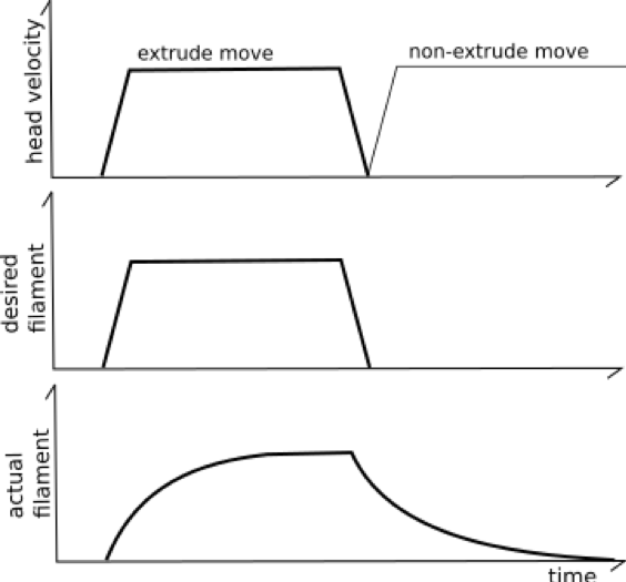
Figure 1 - Printhead pressure without Pressure advance. Source: https://www.klipper3d.org/Kinematics.html
Figure 2 shows the compensation itself. Here, we can see that just before the actual movement, more material is forced into the nozzle to develop sufficient material pressure for subsequent printing. When slowing down, the process is reversed. First, the flow of material in the extruder slows down, which reduces the pressure in the nozzle. Then, when the nozzle is retracted, only the material that is in the nozzle will flow.
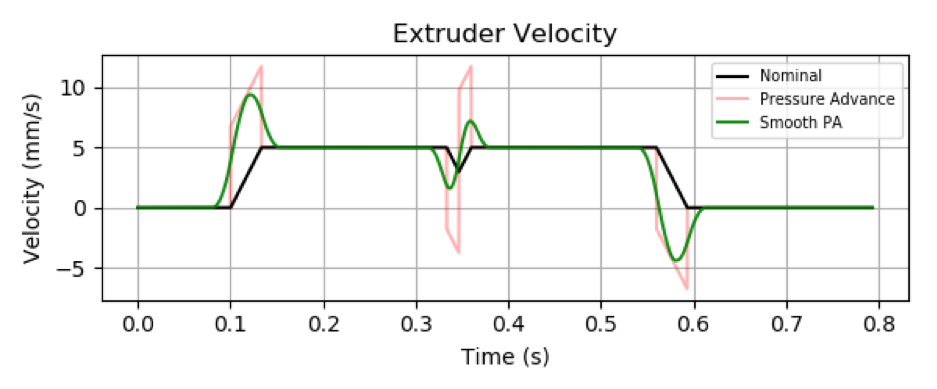
Figure 2 - Pressure advance compensation. Source: https://www.klipper3d.org/Kinematics.html
To ensure that this function works properly, the necessary parameters must be chosen appropriately. These parameters are determined through an experimental method, where an object is printed and the necessary changes are monitored following changes to the Pressure Advance parameter. I followed the instructions from Pressure_Advance and downloaded a cube object that clearly demonstrates these defects.
To print the object, I set the speeds to 100mm/s, used no infill, and set a layer height of 0.3mm (75% nozzle diameter), exactly as recommended. Next, two commands need to be entered into the console. The command “SET_VELOCITY_LIMIT SQUARE_CORNER_VELOCITY=1 ACCEL=500” sets the printer’s acceleration to 500mm/s2, which is a small acceleration to make the flaws more apparent. The second command is “TUNING_TOWER COMMAND=SET_PRESSURE_ADVANCE PARAMETER=ADVANCE START=0 FACTOR=.005”. This command sets the Pressure Advance to zero on the first layer, and then gradually increases it by 0.005 with each subsequent layer. The object can then be printed.
The result is an interesting print, as shown in Figure 3, which immediately indicates that something has changed in the printer settings during printing. I stopped the object intentionally at around 66% of the print, as the additional layers were clearly unnecessary.
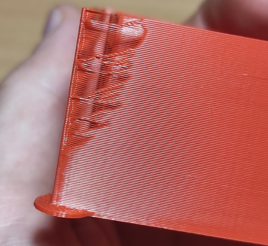
Figure 3 – The result of printing the test object with Pressure advance
From the print, it is evident that although I used a very small increment for increasing the Pressure Advance parameter, its value was already optimal in the initial layers. However, in the higher layers, the nozzle pressure reduction was too great, resulting in material missing in the corners. Now, it is important to carefully examine the print from all angles and identify the layer with the best quality. This layer should have no material loss before or after the corner, and no excess material on the corner itself. Once identified, it is necessary to measure the distance of this selected layer or area accurately from the first layer. I used the slider and obtained a distance of 3.43mm, as shown in Figure 4. This value must now be used in the calculation.
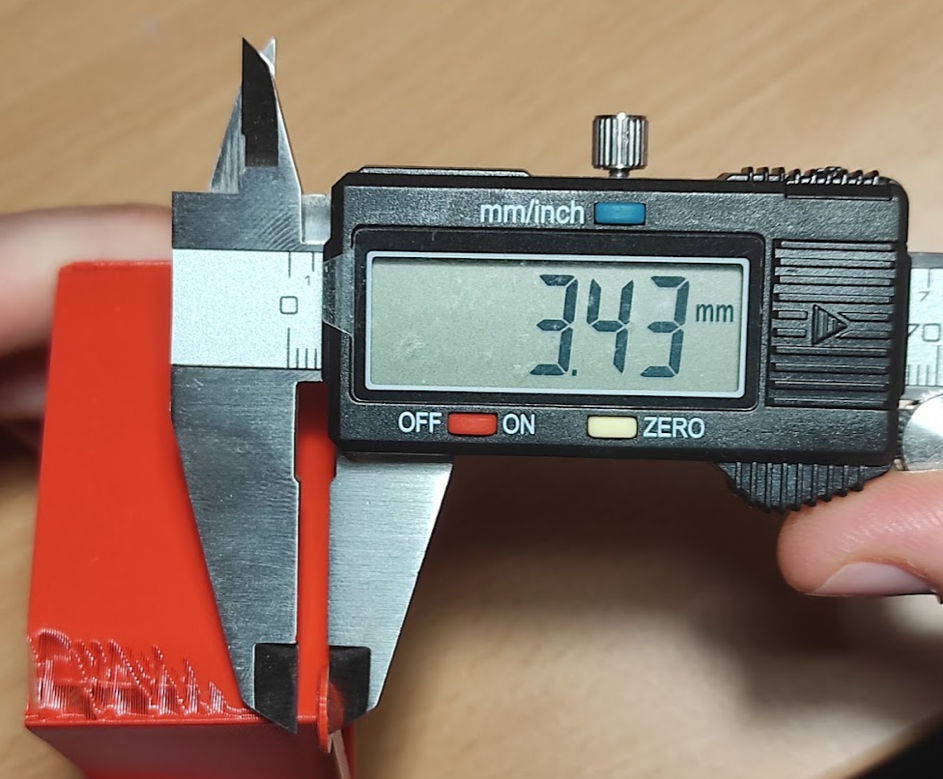
Figure 4 - Measurement of the height of the ideal layer
Parameter Pressure advance PA = (start altitude + measured distance) * selected step in the second command entered into the console. So in my case the calculation is PA = (0+3.43) * 0.005. From this measurement and calculation, the ideal Pressure advance setting for my printer is 0.017. This number is then written to the configuration file in Klipper and it’s done. In my case, since I have a printer equipped with a BIQU H2 direct extruder and I tend to print at lower temperatures, the value of Pressure advance is low.. In the past, when I still had an original extruder with a long bowden on the printer, I had this parameter around 0.4. This means that the compensation had to be more significant.
Resonance Compensation
The second feature to help improve and speed up printing is resonance compensation. With this function, it is possible to eliminate the so-called „ghosts“ in Czech, a surface print defect characterized by the repetition of some print structure. Typically, corners can still be seen several times on the surface of the resulting print in the printing direction. This compensation for the visual surface defect is shown in Figure 5. Mechanical vibrations of the printer itself, caused by factors such as low stiffness of the frame and poorly stretched belts, are responsible for these defects. The vibrations are dependent on the moving mass, especially on the print head. The heavier the print head and the less rigid the structure, the more noticeable the defects and the greater their number.
A possible solution without interfering with the firmware is to lighten the print head as much as possible and reduce acceleration during printing. However, Klipper can eliminate these printer defects. Following a similar principle as in the case of Pressure Advance, these frequencies are measured using an experimental method, and Klipper can compensate for them by subsequently choosing suitable parameters. The second option is to use the accelerometer measurement method, which unfortunately I do not own.
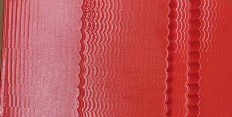
Figure 5 - „Ghosts“ on the print
To set up resonance compensation, I followed the instructions on the page Resonance_Compensation. This page provides a model and a list of print parameters that can be used to set up compensation. To achieve high-speed printing, we need to disable padding and acceleration control in the slicer. We can choose the appropriate printer setting by changing acceleration on the individual parts of the printed object. It is also important to orient the object correctly on the mat, as the X/Y marks are used to set the parameters for the respective planes of the printer.
To set up the printer, we used the following commands. The first command is “SET_VELOCITY_LIMIT ACCEL_TO_DECEL=7000”, which increases the maximum acceleration of the printer to 7000mm/s2. The next command is “TUNING_TOWER COMMAND=SET_VELOCITY_LIMIT PARAMETER=ACCEL START=1500 STEP_DELTA=500 STEP_HEIGHT=5”. This command increases the acceleration from 1500mm/s2 to 500mm/s2 every 5mm of print height during the print. For example, the first 5mm of the print will be set to 1500mm/s2 and the last 5mm will be printed at 7000mm/s2 if the printed object has 12 parts of 5mm each. Once the setup is complete, we can print the test object.
Printing is very fast, and we can take measurements within 30 minutes. To determine the frequency of oscillation that causes the ghosts mentioned above, we need to measure as many ghosts as possible using a slider. The principle of frequency reading is to measure the width of a number of ghosts (oscillations) on the print, as seen in Figure 6.
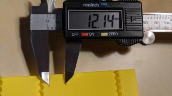
Figure 6 - Measurement of oscillations. Source: Resonance_Compensation
We have to measure for both axes. In my case, I got a distance of 15.25 mm for 8 oscillations for the Y-axis. To calculate the frequency in Hz, use the formula: f = (v * n) / d, where “v” is the printing speed in mm/s, “n” is the number of oscillations, and “d” is the total measured distance in mm. After substituting my values, fy = 100 * 8 / 15.25 = 52.459 Hz.For the X-axis, I measured a value of 12.92 for 7 oscillations (the attached picture of the measurement is not mine). The resulting fx frequency was 51.99 Hz. These values are then inserted into the printer.cfg configuration file. So, under the [input_shaper] header, we insert the corresponding frequency for each axis. In my case, the lines look like this: shaper_freq_x: 51.99 and shaper_freq_y: 52.46. With these parameters, the config is saved, and testing continues.Another parameter that affects the effect of this compensation on the final print is the type of compensation. Klipper supports two basic types – MFA and EI. Each compensates for these resonant frequencies differently, so it’s worth trying both. Using the command “SET_INPUT_SHAPER SHAPER_TYPE=MFA” and “SET_INPUT_SHAPER SHAPER_TYPE=EI”, we print the test object twice more. We then compare the results with the original print to see if there really has been an improvement. If so, we measured the oscillations correctly and then compare the two new prints with each other. If we do not see a significant difference between them, we will choose the MFA input shaper. The latter has the advantage over EI in that it has less effect on the printed object. In other words, the EI shaper will affect the shape of the resulting object more. This was also my case, which is why I added the “shaper_type: MFA” parameter to the config for the frequencies for individual axes. If resonances appear even after setting the resonance frequencies in the config, it is advisable to repeat the measurement. Figure 7 shows a comparison of my prints before and after compensation. The top of the image is always the original print without compensation, and the bottom is the print with compensation.
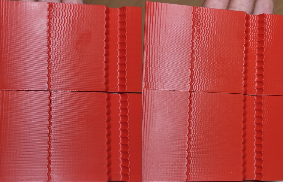
Figure 7 - Comparison before and after compensation (Y-axis on the left and X-axis on the right)
In Figure 7 on the left, which shows the Y axis, a huge improvement can be seen after adjusting the compensation. Even with an acceleration of 7000 mm/s2, the oscillations are barely visible, which I consider a great success and confirmation that I measured correctly. As for the image on the right, which shows the X-axis, the improvement is also evident, but the result is not as good as for the Y-axis. The reason could be an inaccurate measurement or an inappropriate type of compensation. To achieve better results, it is ideal to repeat the procedure or use an accelerometer, which can measure frequencies with significantly greater accuracy. However, this experimental method is sufficient for rough tuning of the printer.
Another parameter that can be determined during this measurement is the maximum acceleration of the printer. With increasing acceleration, the smoothing of the print increases, and this can affect the final function of the product. For this reason, the test prints need to be examined again. Specifically, we are interested in the wavy part on the left, which divides with increasing acceleration, creating a gap, as shown in the detail of the Y axis in Figure 8. Here, you can see that from about the 5th to the 6th wave, small holes appear from below, indicating that acceleration has a significant effect on the print result. Therefore, if I wanted to maintain print quality and function, I would set the maximum acceleration of the printer to 3500-4000 mm/s2. By the seventh wave (acceleration 4500 mm/s2), the rounding is already significant from my point of view. However, depending on the desired speed of the printer and the quality of the resulting print, everyone can choose the maximum acceleration as they see fit.
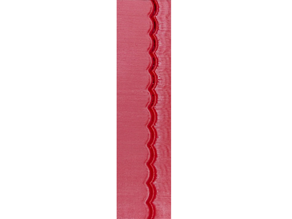
Figure 8 – Formation of a gap – the choice of maximum acceleration
In this article, I have summarized the fundamental features of Klipper. While these features may not seem extraordinary, they serve as the foundation for leveraging the computing power of the Raspberry Pi to take 3D printing to the next level. With the use of Klipper, the resulting print quality is noticeably improved, and the rough tuning process does not require a significant amount of time.
In conclusion, whether you decide to use Klipper or not, 3D printing can be a fun and rewarding hobby. The ability to create your own designs and bring them to life is truly satisfying. With the right tools and a bit of patience, you can produce high-quality prints that look and function exactly as you imagined. And with Klipper, you can take your printing to the next level by harnessing the power of a single-board computer like the Raspberry Pi. So, whether you’re a seasoned 3D printing enthusiast or just starting out, enjoy the process and have fun exploring the possibilities!
Lukáš Žídek